
2nd end receivers
Camera-based receive devices that decode each strand's flash without physical contact. Eye-safe indirect viewing with visual and audible identification, in a tablet family and a smartphone family.
RX-Type 1
Three configurations on a 7-inch tablet
RX-Type 1 family specifications
| Form factor | 7-inch tablet |
| Type 1 | Modified tablet, wired 3.9mm USB custom otoscope with LC tip |
| Type 1A | Generic tablet; otoscope drives a 2.8-inch display read by the tablet camera |
| Type 1B | Generic tablet; passive large-core fiber to the tablet camera |
| Camera | Custom otoscope with near-infrared bandpass filter; WiFi otoscope option |
| Spectrum | Visible and near-infrared |
| App | VisiMap App (receiver and remote control app) |
| Viewing | Eye-safe indirect (screen) |
| Identification | Visual + audible |
| Audio output | Any language or code |
| Connectivity | WiFi, Bluetooth, Cloud |
| Encryption | Custom encryption |
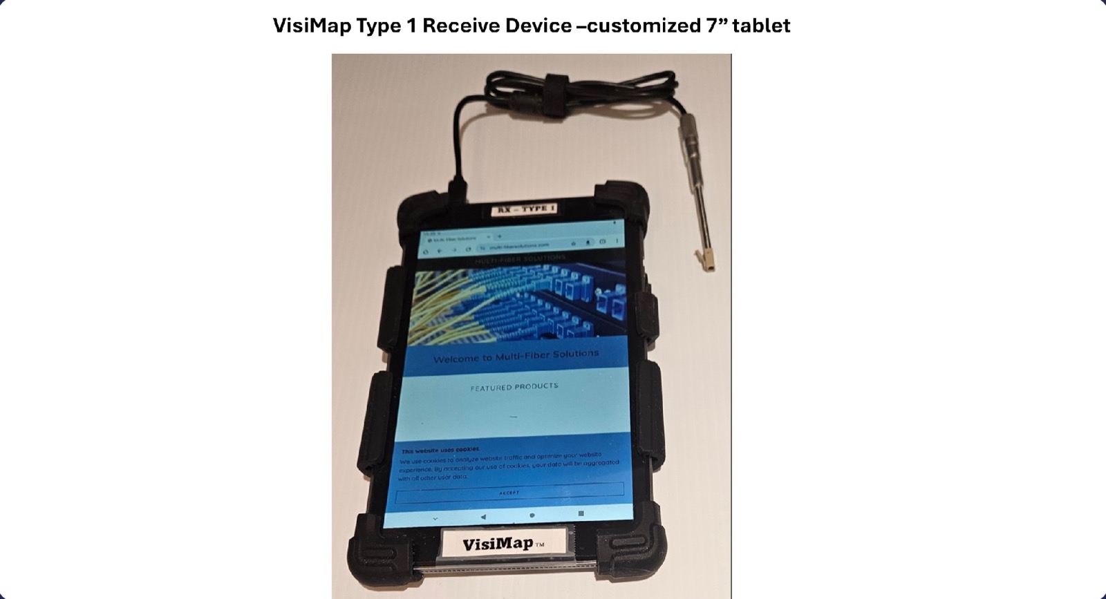
Type 1: modified 7-inch tablet
A 7-inch tablet with a wired 3.9mm USB custom otoscope camera and LC tip. The camera is fitted with a bandpass filter to better capture light in the near-infrared spectrum, which extends decoding far beyond what the visible spectrum allows. The tablet is modified to recognize the otoscope feed as its own rear camera, because the app it runs only recognizes the internal camera. A WiFi otoscope option decodes without contact as well. The otoscope reaches LC or other connectors in tight, high-density locations and side-facing inserts that are impossible to view directly. The technician sees results on the screen and hears each strand announced, never looking at the fiber endface.
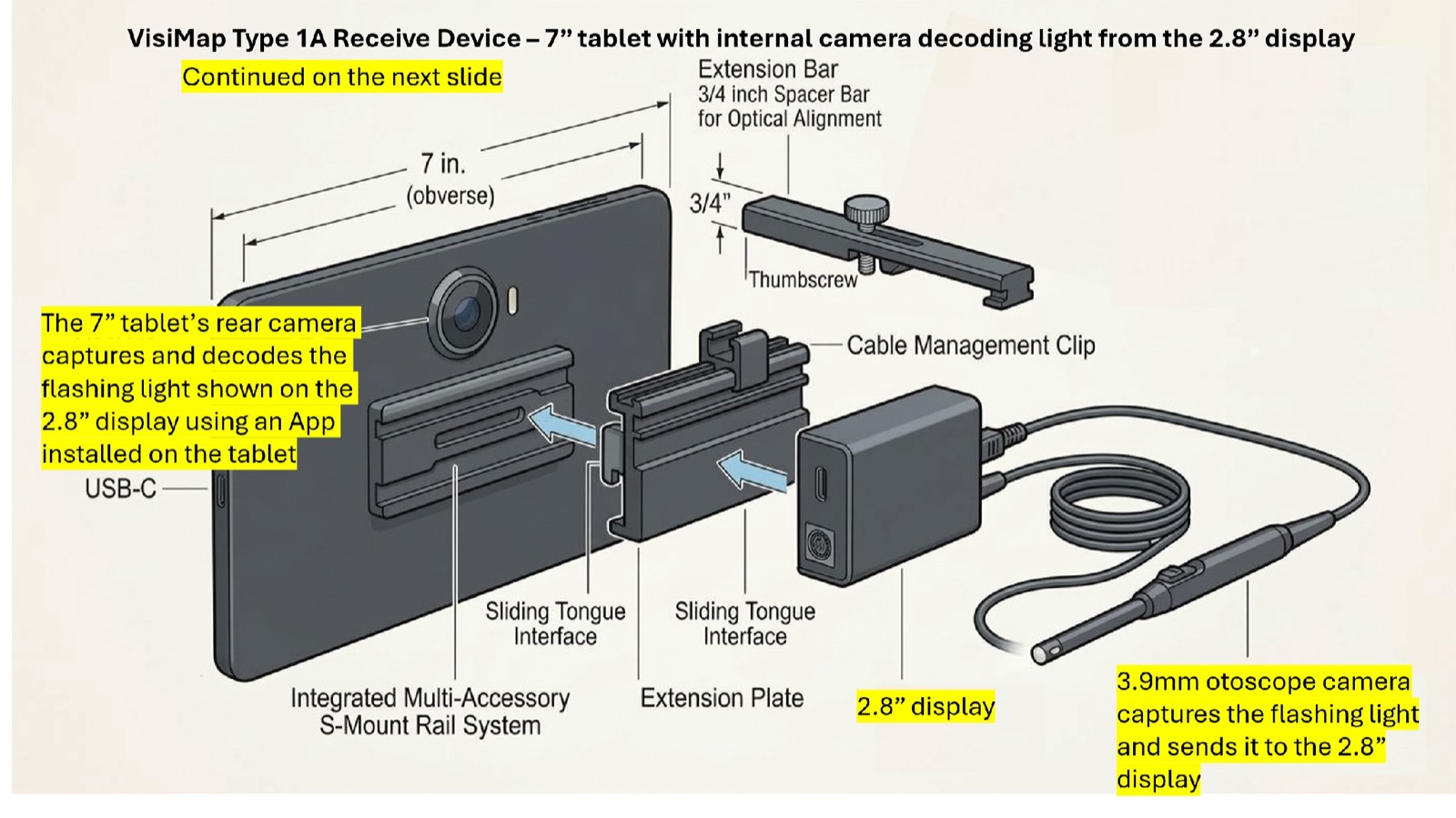
Type 1A: generic tablet with a 2.8-inch rear display
The 3.9mm otoscope captures the flashing light and sends it to a 2.8-inch display mounted on the tablet's S-mount rail, facing the rear camera. The tablet's own camera and an installed app do the decoding, so no tablet modification is needed. A 3/4-inch spacer bar sets the optical alignment.
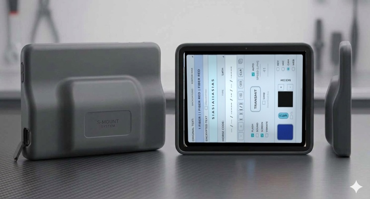
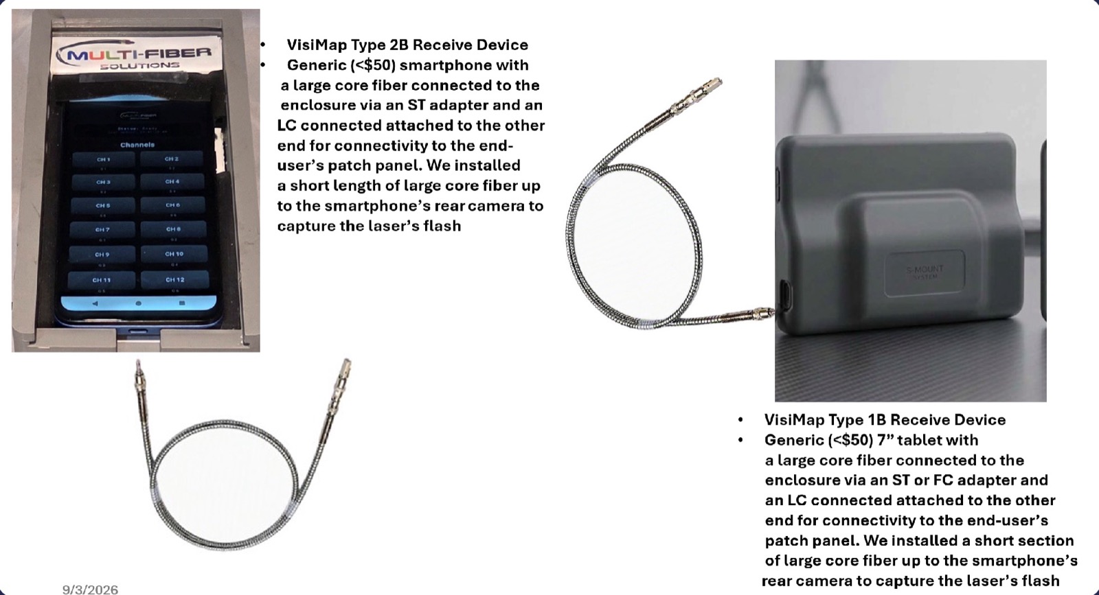
Type 1B: generic tablet with passive large-core fiber
A generic 7-inch tablet with a large-core fiber connected to the enclosure through an ST or FC adapter, and an LC connector on the other end for the end-user's patch panel. A short section of large-core fiber carries the flash to the tablet's rear camera. For use with the laser FCMs.
RX-Type 2
Two configurations on a generic smartphone
RX-Type 2 family specifications
| Form factor | Generic smartphone in VisiMap enclosure |
| Type 2 | Wired 3.9mm USB otoscope with LC tip |
| Type 2B | Passive large-core fiber to the phone camera |
| App | VisiMap App |
| Viewing | Eye-safe indirect (screen) |
| Identification | Visual + audible |
| Audio output | Any language or code |
| Connectivity | WiFi, Bluetooth, Cloud |
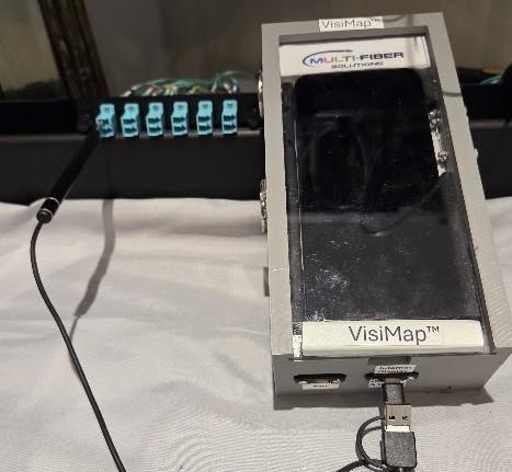
Type 2: generic smartphone with wired otoscope
A generic $50 smartphone with a wired 3.9mm USB otoscope camera capturing the flash. The otoscope's LC tip plugs into the end-user's equipment or patch panel; non-contact decoding removes the risk of cross-contamination. The VisiMap App audibly announces the ID of the fiber strand, and the ID can be user-defined.
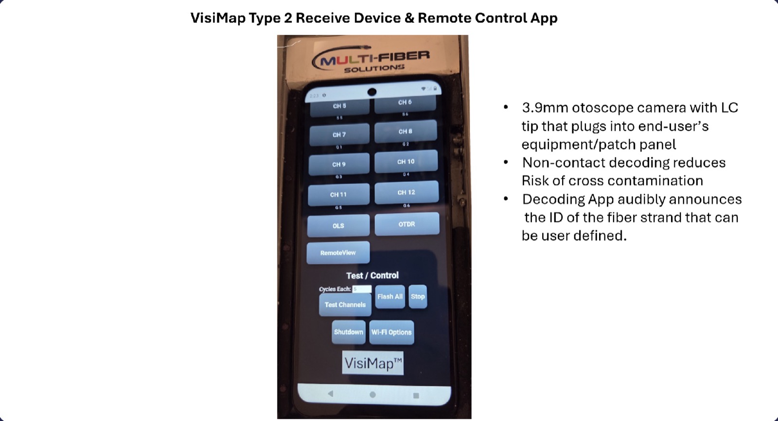
The VisiMap App
One app for both jobs: receiver and remote control. Channel buttons announce and log each strand; the OLS, OTDR, RemoteView, and Test/Control functions drive a Tier 2 system from the 2nd end. It works wirelessly with the 2nd end receivers and can be configured with or without an Internet connection.
Type 2B: generic smartphone with passive large-core fiber
A generic $50 smartphone with a large-core fiber connected to the enclosure through an ST adapter and an LC connector on the other end for the patch panel. A short length of large-core fiber runs up to the phone's rear camera to capture the laser's flash. For use with the laser FCMs.
Large-core fiber instead of a camera cable
For a tablet, smartphone, or custom device with an internal camera.
With the laser FCMs, large-core silica fiber patch cords operating in the 400nm to 2000nm range have excellent transmission in the visible spectrum as well as 1310nm. An LC connector on the end of the large-core fiber plugs into the patch panel, so this is a non-contact 2nd end connection as well. The light travels from the patch panel to a fitting on the enclosure and is aimed at the smartphone or tablet's rear camera. This works very well in both the visible and near-infrared spectrum, costs less, and does not overpower the camera.
Where overpowering the camera is a concern, the large-core fiber is pointed at an infrared alignment card instead. The card makes the IR light visible, and a USB otoscope or webcam aimed at the card does the decoding. The card also reflects visible light, so it works in either spectrum.
Every 2nd end receiver includes
Non-contact identification
Camera-based decoding reads encoded light signatures without physically mating with the connector. No dust cap removal. No contamination risk.
Audible announcement
Strand identification announced out loud in any language or code (“Fiber 1”, “Port A12”, or a user-defined label such as “Blue 1” or “Server 2”), so the technician is certain which cable, buffer tube, or port is associated with each strand. Pair with Bluetooth headphones for noisy environments. Frees hands and eyes.
Built-in documentation
WiFi, Bluetooth, and cloud connectivity capture identification records in real time. Document as you go with 100% confidence.
Wireless and lighting-independent
Untethered operation over WiFi and Bluetooth, with the VisiMap App switching modes at end #1 from the 2nd end, and reliable identification regardless of ambient lighting, indoors or in outside plant.
Which receiver is right for your team?
Our team can help you select the right 2nd end receiver configuration for your deployment requirements.