VisiMap™ Tier 2: Fiber Identification and Remote OTDR Access System
Identification. 2-way communications. Qualification testing. Documentation.
Tier 1 hardware plus plug-in modules on the FCM tap port. One technician, working from the 2nd end, runs identification, fault location, power-loss testing, and OTDR traces at end #1, all on one connection.
VisiMap introduction (lead-in)
VisiMap introduction (lead-in)
Not a fiber identifier. Not an OTDR upgrade.
A single-technician workflow system that fuses fiber identification, communications, remote switching, and OTDR testing into one integrated process.
- Identify
- Connect
- Control
- Test
- Document
Five steps, one technician. The Fiber Control Module sits at end #1. The technician works from the 2nd end (another rack, telecommunications closet, or building) and controls end #1 over the very fiber that was just identified. Each of the 12 fiber strands that have been identified can carry that control, which allows a single technician to do the work of two technicians.
From identification to qualification testing
- Identification
- 2-way communications
- Qualification testing
- Documentation
Tier 2 starts with the same Fiber Control Modules and 2nd end receivers as Tier 1, then adds plug-in modules to the FCM tap port. The Communications & Control Module (CCM) opens a two-way channel between the ends, so a single operator can switch the system from identifier, to visual fault locator, to OLTS (optical loss test set) qualification testing, to OTDR testing, without walking back to the 1st end. Remote OTDR trace viewing lets the technician begin troubleshooting at the 2nd end and work toward the 1st end.
The Optical Light Source (OLS) and OTDR modules turn identification into qualification testing on the same connection: identification, fault location, power metering, and OTDR traces, documented as you go.
Two people, or one person doing the work of two
Traditional multi-fiber testing requires two people, or a single person working the same amount of time as two or more people.
Two technicians and a phone
- Technician at End A
- Technician at End B
- Phone coordination between ends
- Manual fiber identification
- Manual OTDR setup
- Fiber switching at the remote location
One technician, every function
A single technician performs every function from the 2nd end: identification, communications, switching, and OTDR testing at end #1. Nobody stands at the other end of the cable.
Identify, Connect, Control, Test, Document
Five steps, one technician. The FCM stays at end #1; the technician works from end #2 and never walks back.
Identify
A single technician connects the Fiber Control Module (FCM) to 12 strands of a multi-fiber cable. Each strand carries our patented, unique port signature.
Our 2nd end receiver decodes the visible (red) flash and audibly announces the identity of the individual strand. The technician knows with 100% certainty which strand is under test.
Connect
Using our patent-pending tap ports, the technician connects the Communications and Control Module (CCM) to the FCM at end #1. This connection establishes a communications path on any of the 12 strands that have been identified.
At the 2nd end, the technician simply removes the USB otoscope camera that was used to identify the strands and plugs a USB to Ethernet adapter into the same USB port. The twisted-pair output of the adapter connects to a bidirectional media converter with a simplex fiber optic output. The technician has now established the communications path back to the 1st end controller.
Identification mode: the USB camera and 2nd end receiver read the fiber's ID. Communications mode: the USB to Ethernet adapter drives the bidirectional copper-to-simplex media converter.
Control
The technician is now located at the 2nd end (another rack, telecommunications closet, building, etc.) and has a communications path between end #1 and end #2.
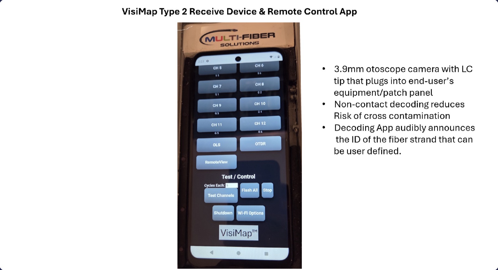
From the VisiMap App (receiver and remote control app), the technician controls the individual lasers at end #1 and any peripheral devices connected to the tap ports.
Test
The technician can turn the VFL function on or off on any, or all, of the 12 strands, initiate an OTDR trace on any identified strand at end #1 from end #2, and view the results of that trace. Shooting an OTDR trace and viewing the results from the 2nd end is extremely efficient, especially in disaster recovery situations.
Because the technician is 100% certain of the identity of each strand at the 2nd end (without that certainty, a loopback test is not valid and the documentation is not accurate), the technician can install a loopback jumper at end #2 and test the entire route of any duplex circuit with the OTDR. Using the remote access capabilities and a fiber optic switch located at end #1, the technician can change fiber strands and shoot an OTDR trace in the opposite direction on a paired circuit.
That provides the information needed to diagnose and repair any faulty link, and the technician can begin troubleshooting at the 2nd end and work toward the 1st end, which saves time, money, and network downtime. The reference configuration tests at 1310nm. With the optional transceiver set, the technician can test bidirectionally at 1310nm and 1550nm and fulfill extended (industry Tier 2 / OTDR) certification requirements.
Document
Accurate documentation is a very important component of a stable fiber optic network. Using our patented system, a single technician can audit the entire cable plant.
The technician can label patched or fusion-spliced connections as they are completed. This is especially important on multi-hop patching through different buildings or cables.
Eleven steps, one person, start to finish
No second technician required.
- Connect the Fiber Control Module at end #1
- Confirm the 2nd end receiver is in sync and announcing
- Connect the camera or 2nd end receiver and decode the signatures
- Receive the audible identification
- Select any one of the 12 identified fibers
- Connect the bidirectional transceiver and establish communications
- Access the switch at end #1
- Connect the OTDR remotely
- Run the test
- Review the trace
- Repeat on additional fibers
What plugs into the tap port
Each module is a separate investment that plugs into hardware you already own.
CCM — Communications & Control
| Provides | 2-way communications |
| Channel | Bidirectional, on the identified strand |
| Remote modes | ID → VFL → OLS → OTDR |
| OTDR viewing | Remote trace display |
| Interface | FCM tap port |
OLS module
| Provides | Power-loss testing |
| Type | Optical Light Source |
| Wavelengths | 1310nm, 1550nm (NIR) |
| Interface | FCM tap port |
| Note | FCM-12VIR internal NIR may replace it |
OTDR module
| Provides | Qualification testing |
| Type | Reflectometer |
| Measurements | Loss, distance, events |
| Interface | FCM tap port |
| Remote viewing | Via CCM channel |
From Tier 1 to Tier 2
Tier 2 is not a different box. It is a Tier 1 Fiber Control Module with modules in its tap port, controlled from the 2nd end.
Tap port ready
The 6-port VFL module ships with the optional tap port that accepts the CCM, OLS, and OTDR modules. Start with six mini-VFLs, expand to twelve, then add modules.
Internal light source
Six near-infrared lasers at 1310nm and 1550nm give the 12VIR an internal light source, so it can stand in for the external OLS module when stepping up to qualification testing.
Controlled from the 2nd end
The VisiMap App carries the OLS, OTDR, and RemoteView controls, so the technician at the 2nd end switches modes and views traces without a second person.
Beyond identifiers and remote OTDR systems
Detect light, not identity
Detect optical traffic, test tones, and direction. They do not assign unique signatures, speak IDs, establish communications, or control resources.
Monitor the network
Built for network monitoring, fault location, and centralized testing. The question they answer is: how can I remotely test fiber?
Identify, control, and test
- Unique identification
- Audible confirmation
- Communications establishment
- Remote testing control
- Single-technician operation
The real question VisiMap answers: “How do I identify the fiber, establish control, and remotely test it without a second technician?”
Six things VisiMap combines
Each one is useful alone. Together they remove the second technician.
Unique optical port signatures
Morse, binary, pulse, encrypted, or time-domain identifiers on every strand.
Camera-based identification
Machine vision and optical observation decode the fiber without contact.
Audible fiber verification
Automatic speech output confirms the identity of each fiber.
Two-way session establishment
Swap the USB camera for a media converter on the identified strand.
Remote resource control
Drive switches, test gear, and end #1 equipment over any identified fiber.
Single-technician operation
The strongest business case: fewer people, faster fixes.
All on one connection
With FCM, CCM, OLS, and OTDR modules connected, VisiMap performs identification, fault location, qualification testing, power metering, and documentation — without disconnecting.
What this means for your team
Traditional workflows require separate test instruments and separate connections for each function. VisiMap's modular architecture consolidates everything into one connection — less connector handling, less contamination risk, less total test time.
Modular investment
Start with identification (Tier 1: FCM plus receiver), add communications (CCM) when ready, add optical testing (OLS, OTDR) as requirements grow.
- Reduced labor costs
- Fewer personnel per task
- Faster outage resolution
- 100% accurate documentation
Build the right system for your team
A single technician uniquely identifies a fiber, audibly verifies it, establishes communications, accesses remote switching and test resources, and completes OTDR analysis, with no second technician at the other end of the cable.