
VisiMap™ Tier 1
Identify. Test continuity. Verify polarity. Document.
Low-cost Fiber Control Modules and eye-safe, non-contact 2nd end receivers. One person identifies, tests, labels, and documents every strand with 100% certainty.
VisiMap introduction (lead-in)
VisiMap introduction (lead-in)
The next-generation must-have tool
- Identify
- Test continuity
- Verify polarity
- Document
Tier 1 highlights
- Eye-safe, non-contact viewing — zero direct laser exposure
- Low cost
- Multi-colored light sources
- Customizable, per-strand encrypted identification
- Non-contact 2nd end receiver with audible, verbal announcement of each strand
- Optional WiFi otoscope camera and Bluetooth ear buds for untethered work in dense or messy racks and patch panels
The VisiMap Tier 1 product line consists of low-cost Fiber Control Modules (FCMs) that send our patented, visible-spectrum, multi-colored flash, combined with our unique port signature method, to a 2nd end receiver. A single person can identify, test for continuity and polarity, label, and document the results with 100% certainty. We add encryption to the low-frequency flash, and our 2nd end receiver uses a number of patented, eye-safe, non-contact methods to decode the incoming flash. This allows us to substitute a short burst for a predefined word or phrase. Once the message has been decoded, the 2nd end receiver audibly announces the identity of the fiber (“Fiber 1”, “Port A12”, or a user-defined label such as “Blue 1” or “Server 2”), so the technician is certain which cable, buffer tube, or port is associated with each strand.
The Visual Fault Locator (VFL) has been the go-to tool for many decades. The VFL uses a high-intensity visible red laser beam to find breaks, sharp bends, kinks, bad splices, and faults through the cable jacket on an individual strand. However, many technicians rely on the VFL as the primary method of identifying an individual fiber by looking at the end of the strand, which can be a safety concern.
Many VFLs sold today are far more powerful than their labels say. See why that matters on the Safety page.
The VisiMap suite of products builds on the desirable features that VFLs offer, while providing a way to overcome the shortcomings of the single VFL. Multi-Fiber Solutions has developed the next-generation must-have tool.
Every Fiber Control Module at the 1st end sends a unique, encrypted port signature. Every signature is decoded by a 2nd end receiver.
Tier 1 Fiber Control Modules
The Essential level is the LED module with zero laser risk. The Advanced level is the visible-laser family, with longer single-mode reach and the tap port that steps up to Tier 2.
12-port LED module
LED-based encoded identification for any cable type. Low cost, ideal for data centers. Multimode applications up to 1 km and single-mode up to 2 km. Removes laser risk entirely. Modular and expandable to 24, 36, or 48 ports.
6-port VFL module
One for every tech: keyed, proprietary pen-style mini-VFLs, field-expandable to 12 ports. The FCM supplies the power and the flash sequence, so there are no batteries and modules swap in the field. Optional tap port for the Tier 2 CCM, OLS, and OTDR modules.
12-port visible laser
Visible laser module with encoded signatures at 520nm and 650nm wavelengths via DMX512 protocol.
12-port visible + infrared
6 visible and 6 NIR lasers. The internal NIR light source replaces the external OLS module.
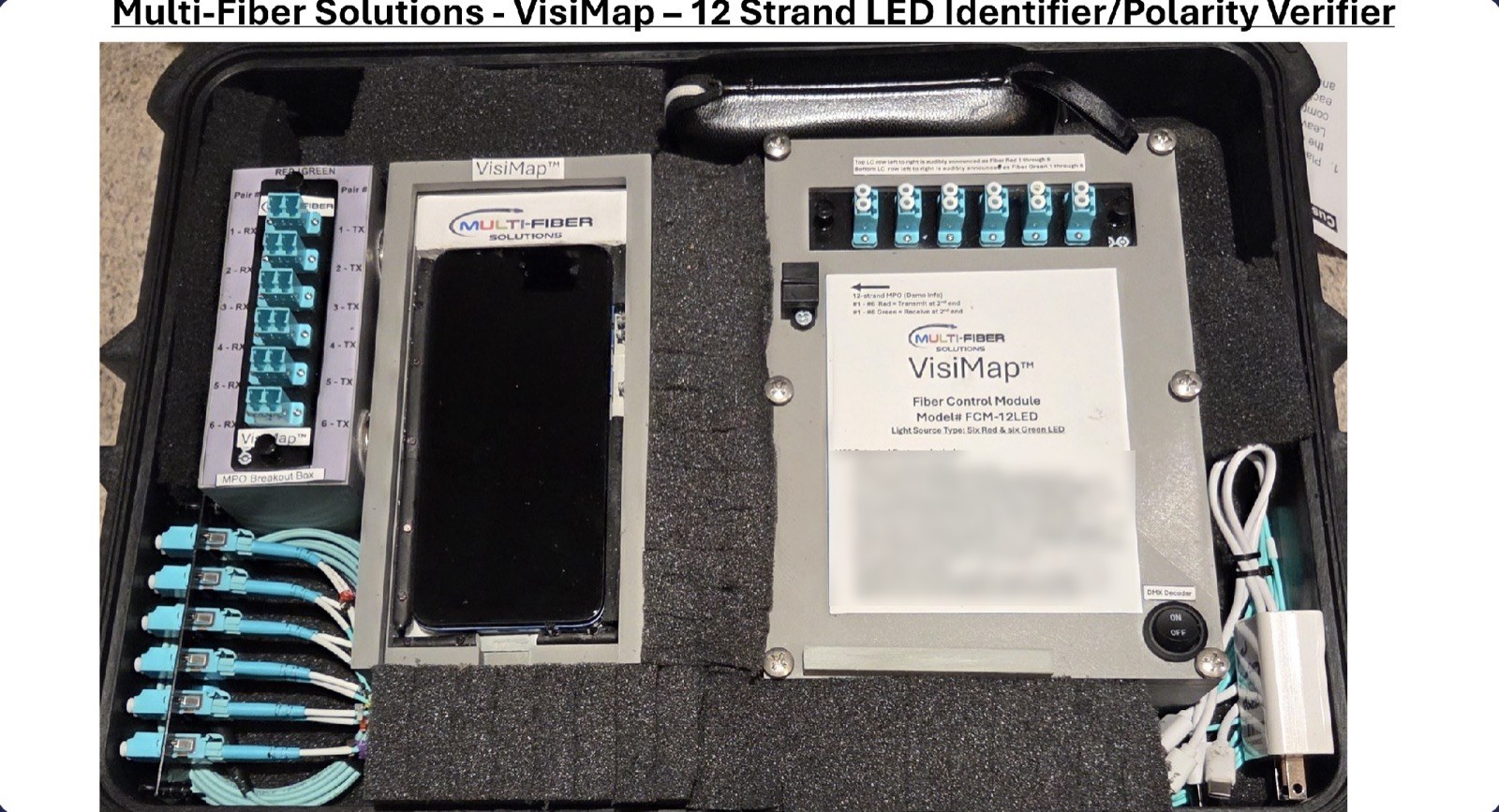
The 12-strand LED identifier and polarity verifier
The FCM-12LED kit: Fiber Control Module, 2nd end receiver, and MPO breakout box. Confirms continuity on any strand from point A to point B in any multi-fiber cable, MPO or non-MPO. Verifies TX and RX polarity in duplex deployments using red and green. Field-configurable in about two minutes to an MPO cable or any simplex or duplex connector.
2nd end receiver options
Every receiver reads the flash with a camera, never with the technician's eye, and announces the strand out loud. Two families: the 7-inch tablet (Type 1) and the generic smartphone (Type 2).
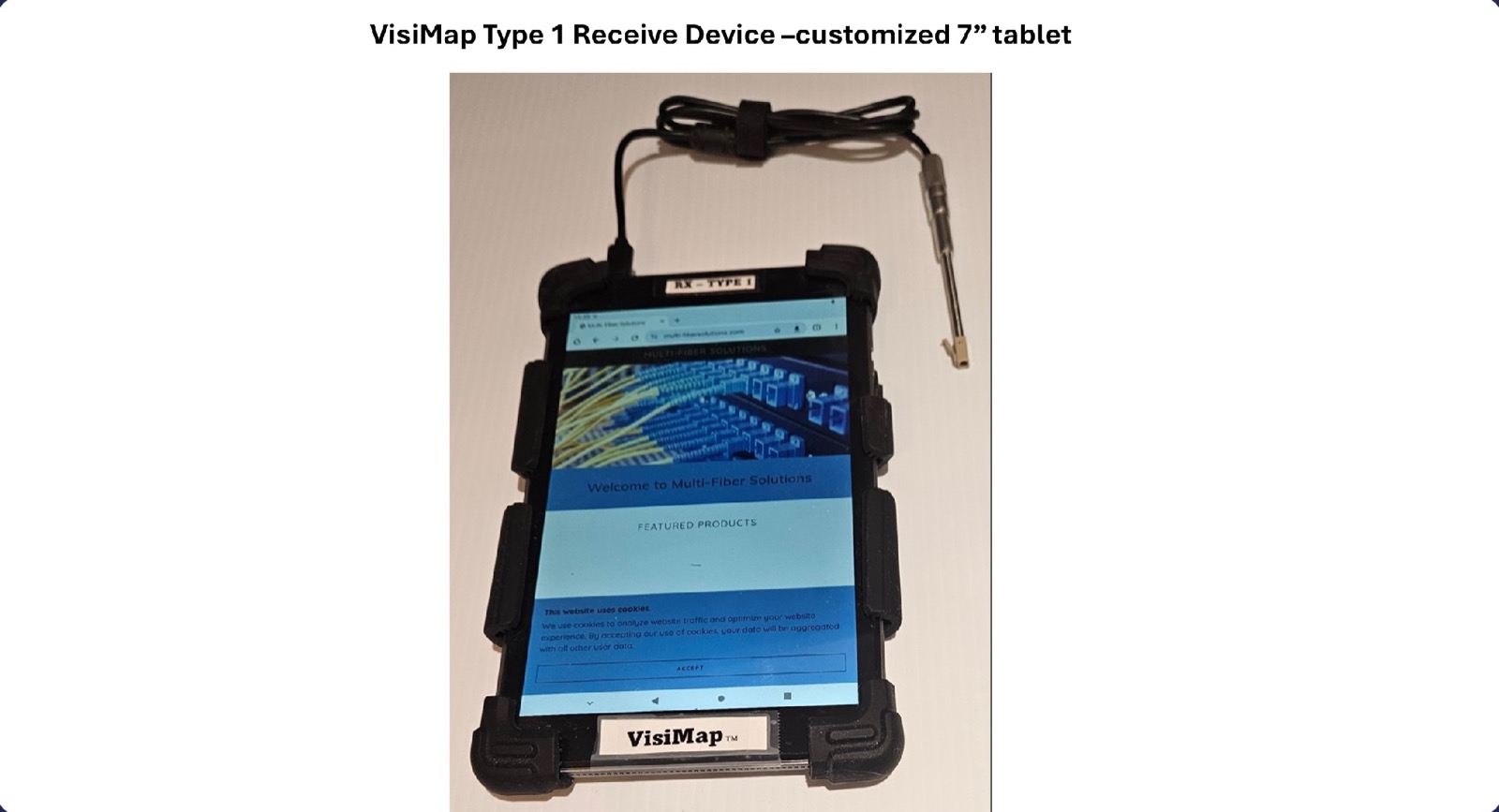
RX-Type 1
A 7-inch tablet with a wired 3.9mm USB custom otoscope camera and LC tip. The camera is fitted with a bandpass filter to better capture light in the near-infrared spectrum, which extends decoding far beyond what the visible spectrum allows. The tablet is modified to recognize the otoscope feed as its own rear camera, because the app it runs only recognizes the internal camera. A WiFi otoscope option decodes without contact as well. WiFi and Bluetooth for untethered use in racks and patch panels, with cloud-connected documentation.
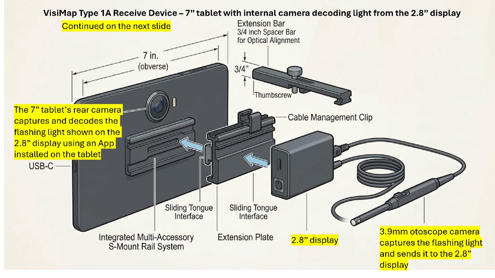
RX-Type 1A
A generic 7-inch tablet whose own rear camera does the decoding. The 3.9mm otoscope captures the flash and shows it on a 2.8-inch display that mounts on the tablet's S-mount rail, facing the rear camera. No tablet modification needed.
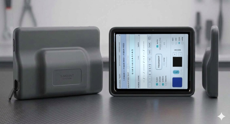
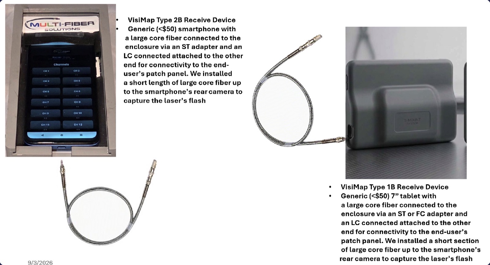
RX-Type 1B
A generic 7-inch tablet with a large-core fiber connected to the enclosure through an ST or FC adapter, and an LC connector on the other end for the patch panel. A short section of large-core fiber carries the flash to the tablet's rear camera. For the laser FCMs.
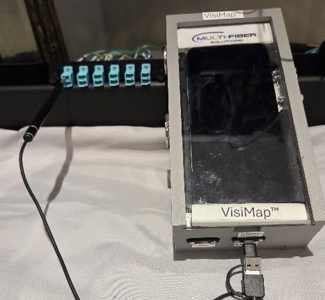
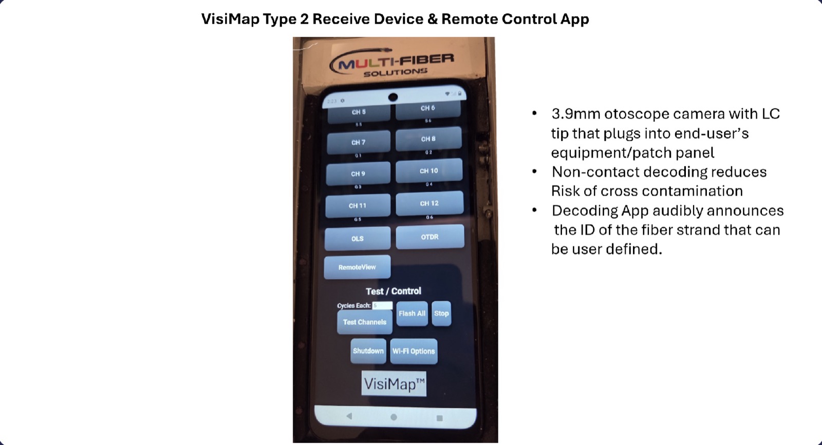
RX-Type 2
A generic $50 smartphone in a VisiMap enclosure with a wired 3.9mm USB otoscope camera capturing the flash. The 3.9mm otoscope with LC tip plugs into the end-user's equipment or patch panel; non-contact decoding removes the risk of cross-contamination. Runs the VisiMap App.
RX-Type 2B
A generic $50 smartphone with a large-core fiber connected to the enclosure through an ST adapter and an LC connector on the other end for the patch panel. A short length of large-core fiber runs to the phone's rear camera to capture the laser's flash. For the laser FCMs.
Large-core fiber, no camera cable
In addition to the wired otoscope receivers, there is a passive option for a tablet, smartphone, or custom device with an internal camera. With the laser FCMs, large-core silica fiber patch cords operating in the 400nm to 2000nm range transmit the visible spectrum and 1310nm. An LC connector on the panel end makes this a non-contact 2nd end connection as well. The light runs from the patch panel to a fitting on the enclosure and is aimed at the device's rear camera. It works in both the visible and near-infrared spectrum, costs less, and does not overpower the camera.
Where camera saturation is a concern, the large-core fiber is pointed at an infrared alignment card instead, which makes the IR light visible on the card, and a USB otoscope or webcam reads the card for decoding. The card also reflects visible light, so it works in either spectrum.
See Tier 1 at work
Three short introductions, in order: the FCM-12LED, VisiMap in the data center, and a technician using the FCM-12LED. The fourth video in the series, VisiMap & Eye Safety, is on the Safety page.
Ready for Tier 1, or need Tier 2?
Describe your plant and our team will recommend the right Fiber Control Module and receiver.